This is a progress report for a little 5W amplifier that I’m designing and building.
Some key elements of the design:
- Single-ended MOSFET output stage
- 2A high-side current source
- 0-20V rails and approximately +/-5V usable output before soft clipping into 8 ohms
- Long-tailed pair gain stage, KISS principle
- DC-blocking output capacitor
- Current feedback
- Ultra-low noise
Basic schematic*:
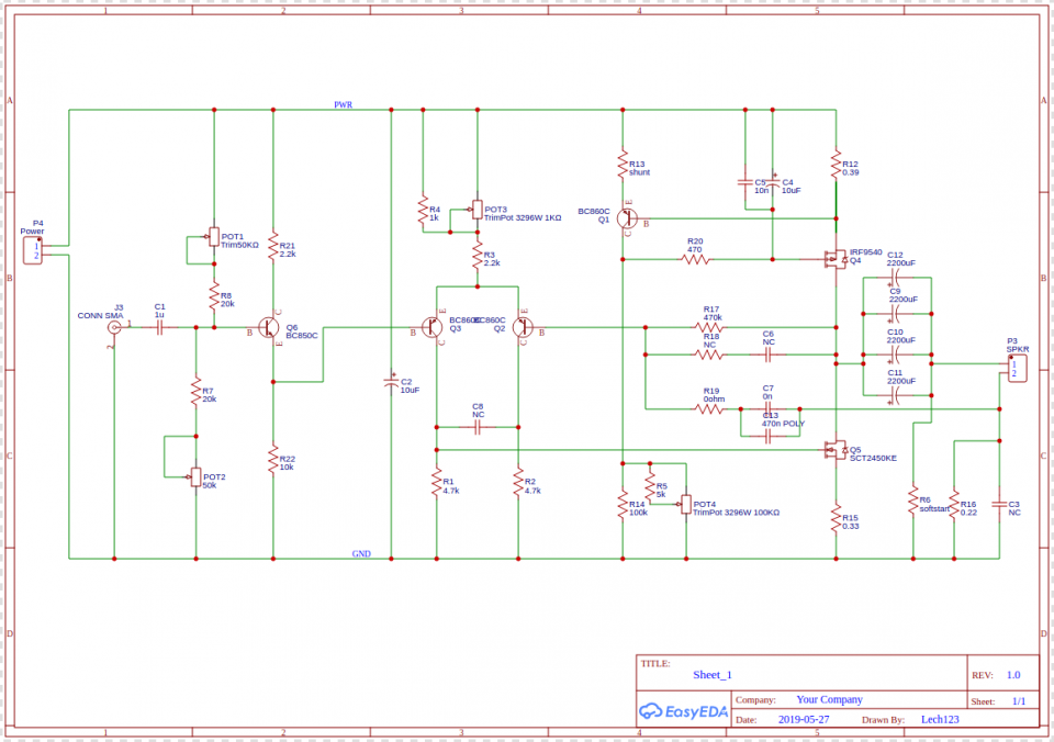
*Note the asterisk:
Component values, their exact location, and board layout are all subject to tuning, experimentation, and general debugging. It’s a prototype after all. There is no power supply, yet. Although I could use a standard, bulky transformer based thing, initially it will be powered by a bench-top PSU, and I’m keen to investigate if an SMPS can be filtered and made quiet enough for the job.
The decision to post this schematic was difficult for me. It was a lot of work, but at the same time, I consider it to be entirely based on well-known design ‘blocks’.
Simulated performance
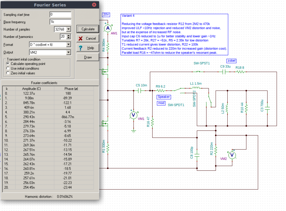
I took care to a use a (RL + |LCR|) speaker model, rather than an 8 ohm resistor load. With this I was able to see that flattening the impedance with a Zobel network helped to improve distortion to <0.05%THD @ 1kHz, with 10mV in, 250~300mV out depending on gain settings.
A particularly good ‘tune’ in TINA had 0.016% THD, but I consider it be unrealistic because it relied on an ideal signal source with low output resistance. Headphone outputs from a sound-card or may get close, but if other devices are used, then variation is to be expected. There is also potential for cancellation of distortion by fine-tuning the current source. Early on, I set R14 (collector side of Q1) to a low value like 1k ohm, but was forced to increase it to prevent overheating, but as I did so, distortion went down instead of up. Adding C4 also improved ripple rejection at high frequencies.
Why current feedback?
This decision came on the back of various anecdotes that tube amplifiers often had the ability to “sound better”, despite their other shortcomings. The idea that harmonic distortion somehow makes the sound pleasantly coloured did not convince me. There had to be more to it. Other people were tentatively suggesting that a ‘low’ damping factor could improve the sound, and the clincher for me was Esa Meriläinen’s www.current-drive.info site, which I found compelling. I’d already achieved some subjective improvement with class-D powered computer speakers by adding 10 ohm resistors in series.
Why a long-tailed pair?
One reason is that the output MOSFET is a very light load, so it seems like a good fit for something as ‘delicate’ as an LTP. The gate voltage for the SCT2450 is a bit high (9~10V) possibly the LTP a bit unbalanced, but I was able to get good distortion figures, and I’m not too bothered if the quiescent output voltage isn’t exactly 10V.
Why not push-pull?
Mainly for the distortion profile. I wasn’t convinced that reducing even-order harmonics would be beneficial, and there would be added costs, like new sources of distortion. As it stands, the design has a steady 2A load. Reducing the quiescent current at low signal levels would mean that the PSU current is modulated by a highly distorted rectified audio signal, and corrective measures would have to be taken.
Other thoughts for today
I’m not sure about the idea of using a giant <0.5°C/W passive heatsink to dissipate 40W (× whatever number of channels). Unless there’s some technical reason to avoid a CPU-style cooler with a low-speed fan, I’m tempted to do that. What about balancing the heat output? As Q4 gets hotter, Q5 cools down, and v.v. Is a heat sink likely to be fast enough to allow some performance advantages? I’m not sure, yet.
Resonance peaks
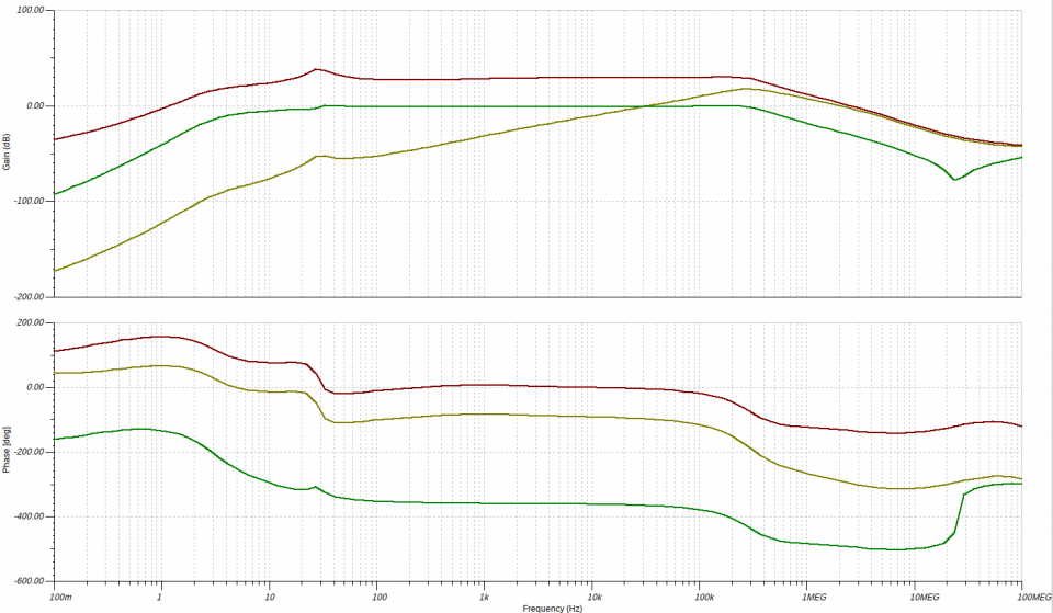
The red curve is VM1, and green is VM2. Yellow is current ripple, but it’s based on an earlier version without C4.
There is a noticeable peak around 27Hz. It’s a (hopefully minor) limitation of this design, related to the LCR speaker load. The high reactance reduces the amount of feedback, increasing the gain and distortion. I played around with some bridged-T notch filters, but it might not be a real problem. A parallel resistor, R16, damps it a bit as well.